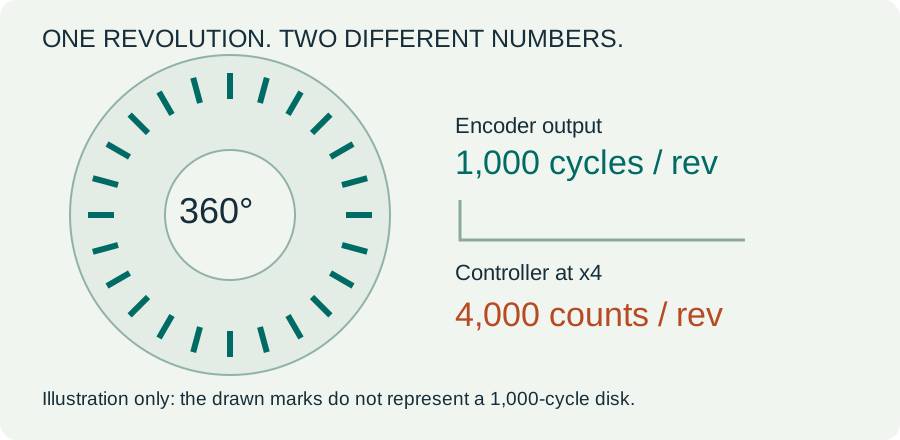
Start with the definition, not the abbreviation.
A number such as “1,000 PPR” is useful only when its meaning is clear. In this guide, P is the number of complete output cycles per revolution on one channel. It is not the sum of A and B or their complementary outputs.
| Term | What it can mean | What to verify |
|---|---|---|
| PPR | Pulses per revolution; some manufacturers use it for the count after quadrature. | Before or after x1/x2/x4 decoding? |
| CPR | Cycles per revolution or counts per revolution. | Channel cycles or decoded events? |
| LPR | Physical lines per revolution on an optical disk. | Does the encoder interpolate before producing its output? |
| Resolution | Smallest digital position increment available. | At the encoder, controller or measured load? |
Same Sky uses PPR for channel pulses; US Digital’s explanation uses CPR for output cycles and PPR for counts after multiplication. That difference is a reason to ask for the waveform and datasheet definition before comparing two products. [1] [2]
Ask the supplier: “Is your resolution number measured before or after quadrature decoding?” For an existing machine, also check how the PLC, counter or drive is configured.
One encoder. Three counting modes.
A and B are typically offset by 90 electrical degrees: one quarter of a signal cycle. The controller uses their order to detect direction. Under the ideal quadrature assumption, counting more edges gives more digital position increments.
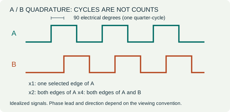
Angular count step = 360° ÷ (P × M)
P = channel cycles/rev; M = 1, 2 or 4
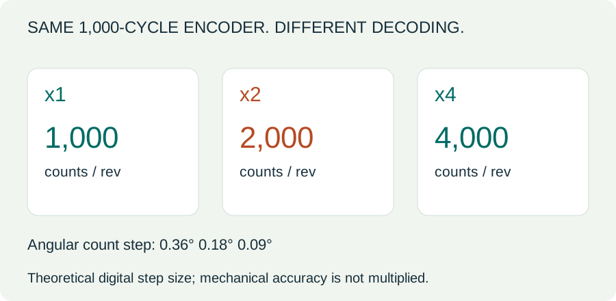
Resolution is not accuracy. A finer digital step does not remove disk error, shaft runout, backlash or wheel slip. If a vendor already quotes decoded counts, do not multiply that value again.
Calculate counts, step size and frequency.
Enter output cycles per revolution before decoding, not an ambiguous PPR/CPR number. Results assume ideal A/B quadrature at the encoder shaft, without a gearbox ratio or wheel slip.
For a 1,000-cycle encoder at 3,000 RPM with x4 decoding: 4,000 counts/rev, 0.09° per count, 50 kHz per channel and 200,000 counts/s. The calculation describes signal rates and digital increments, not a confirmed part selection.
Higher PPR can exceed a hardware limit.
Output frequency grows with both resolution and speed. Check the encoder’s maximum output frequency and the receiving hardware’s input limits. A rating labelled “50 kHz” may describe channel cycles, decoded counts or a particular input mode; read its definition.
Decoded count rate (counts/s) = P × M × RPM ÷ 60
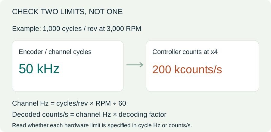
Dynapar describes the relationship between incremental resolution, maximum RPM and output-frequency capability. Actual selection must also account for the receiver’s pulse-width requirements, filters and electrical interface. [3]
Replacing an installed encoder? Start by matching its confirmed output-cycle resolution and decoding configuration. A different resolution can change distance scaling, speed readings and machine behavior unless the receiving system is correctly reconfigured.
For a measuring wheel or screw
Theoretical linear step = travel per load revolution ÷ (P × M × i), where i is encoder revolutions per load revolution. For a direct-driven wheel, travel is π × wheel diameter. For a screw, use its lead. This calculation does not account for slip, backlash or transmission error.
Match the whole encoder, not just PPR.
Two encoders with matching resolution can still have incompatible voltage, outputs, pinouts or mounting. EncoderCross works with selected replacement directions; suitability depends on the original full model and the receiving system.
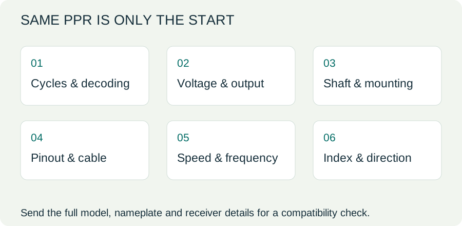
| Send us | What it helps confirm |
|---|---|
| Full model and nameplate photo | Original series, output suffix and stated resolution. |
| PLC, counter or drive model | Decoding, input levels, filtering and frequency limits. |
| Voltage, output type and pinout | NPN/PNP, push-pull or differential compatibility; wire colours alone are insufficient. |
| Shaft/bore, flange and connector | Mechanical fit and electrical connection. |
| Maximum speed, Z-index needs and quantity | Operating conditions, homing requirements and quotation scope. |
Send the details.
We’ll check the replacement direction.
Tell us the full original model and the device reading its signals. We can use those details to assess a candidate and identify what still needs confirmation before quotation.
Before you order.
Does 1,000 PPR always mean 4,000 counts/rev?
Only if the stated 1,000 means output cycles per revolution and the receiver uses x4 decoding. A supplier may use PPR differently, or the receiver may use x1 or x2. Confirm both.
Should I add A, B, A-not and B-not?
No. Complementary outputs are signal inversions used by differential interfaces, not independent resolution multipliers. Define the channel cycles and the receiver’s counting mode.
Will more PPR make my machine more accurate?
It can reduce the theoretical digital step, but does not establish actual accuracy. Mechanical errors, signal quality and the system’s calibration still matter.
Can I use a 1,024-cycle encoder instead of 1,000?
At the same decoding setting, counts per revolution change by 2.4%. That changes scaling. Do not treat the parts as equivalent without confirming receiver configuration and all mechanical/electrical requirements.
Is the Z index included in the PPR total?
For many incremental encoders, Z is a separate reference event rather than additional position counts. Its availability, pulse width, gating and receiver use must be checked for the actual model.
Technical references.
The terminology comparison was checked against manufacturer explanations. Formulas and illustrations use the explicitly stated channel-cycle convention; all numerical examples are calculations, not claims about a stocked product.
- Same Sky: PPR, CPR and LPR definitions
- US Digital: native, interpolated and multiplied resolution
- Dynapar: calculating encoder resolution and frequency constraints
- Precision Microdrives: quadrature and counting conventions
Confirm the original encoder datasheet and receiving-device manual for an actual replacement. Illustrations are original schematics, not installation instructions.