Decode the resolution before comparing models
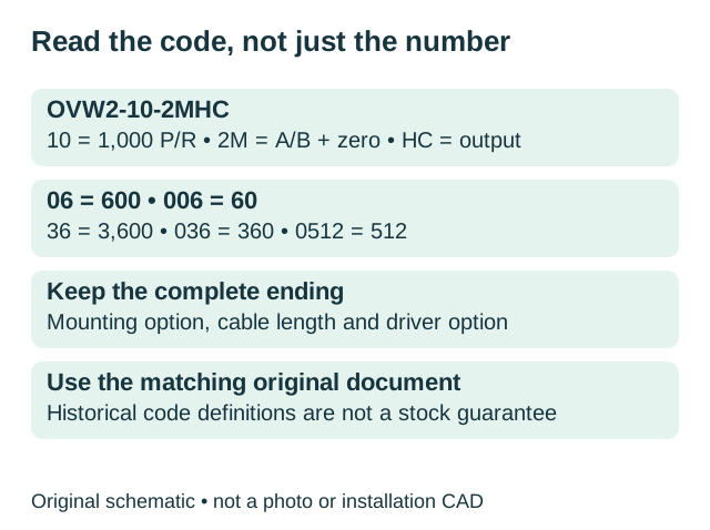
Nemicon’s reviewed catalog prints the family as OVW-2 and uses OVW2 in the ordering code. OVW2-10-2MHC means 1,000 P/R, A/B with a zero signal, and the HC output circuit. It is not a 10 PPR encoder.
| Code | P/R | Do not confuse with |
|---|---|---|
| 006 | 60 | 06 = 600 |
| 036 | 360 | 36 = 3,600 |
| 10 | 1,000 | The literal number 10 |
| 0512 | 512 | A different trailing code |
| 1024 / 2048 | 1,024 / 2,048 | Other codes use a different numeric scale |
P/R here means pulses (cycles) per revolution of one channel; the calculator calls this PPR. The signal code 2 means A/B; 2M adds a zero signal (Z), used as an index reference. Historical cable codes 050, 100 and 300 mean 500, 1,000 and 3,000 mm. Additional fields describe the mounting and D-output option. Retain the entire label, including any D-output LS / C-MOS option, rather than guessing an ending. The code aid does not approve those trailing fields.
Original-code reading aid
Reads the historical resolution and output fields only. It does not validate all orderable combinations, trailing options or an offered replacement.
HC, HCP, HT and D need different checks
| Output | Original circuit | Original supply | Response |
|---|---|---|---|
| No circuit suffix | Voltage output | 4.5–13.2 VDC | 200 kHz |
| C | Open collector | 4.5–13.2 VDC | 200 kHz |
| HC | NPN open collector, high-voltage version | 10.8–26.4 VDC | 200 kHz |
| HCP | PNP open collector, high-voltage version | 10.8–26.4 VDC | 50 kHz |
| HT | Push-pull, high-voltage version | 10.8–26.4 VDC | 200 kHz |
| D | Line driver; LS or C-MOS option | 5 V nominal; check the option’s exact range | 200 kHz |
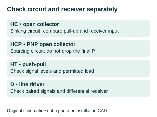
Supply voltage and signal level are different checks. Compare the controller’s circuit, permitted input voltage, load, required channels and counting mode. A 2MD configuration uses paired A/A-bar, B/B-bar and Z/Z-bar signals. A-bar is the complementary signal to A, not a decoding multiplier. Do not assume a receiver accepts paired channels as single-ended A/B/Z.
Map signal functions using each exact document. Do not transfer wire colors or pin numbers between brands. Isolate power before inspection or reconnection, and follow the product and machine instructions for shielding and grounding.
Check the mounting option, not just body diameter
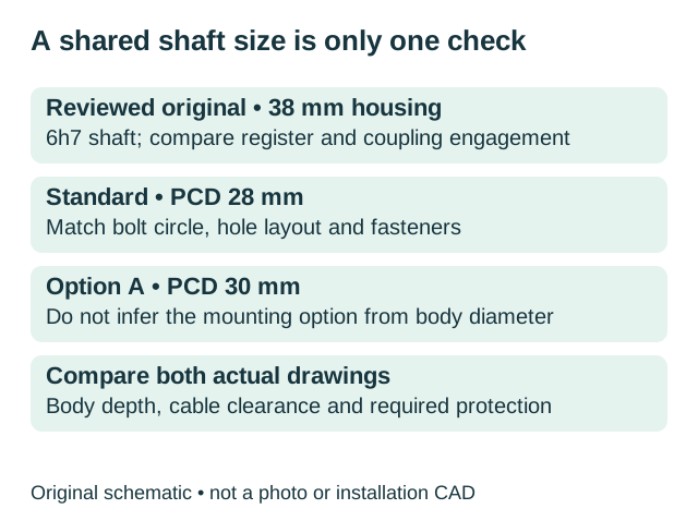
The original drawing shows a 38 ±0.5 mm housing, 6h7 shaft and 20h7 locating register. Standard mounting uses a 28 mm pitch circle; option A uses 30 mm. Compare hole layout, fasteners, shaft engagement, body depth and side cable clearance on both drawings.
The reviewed original specifies IP50 and a 6,000 rpm mechanical ceiling. Neither value automatically applies to the candidate. Confirm the environment and actual working point separately; the signal-rate ceiling can be lower than the mechanical limit.
Request a drawing and interface comparisonCalculate the signal rate at your working speed
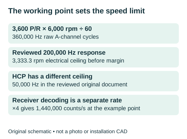
Raw A-channel frequency f = PPR × rpm ÷ 60, in Hz. Receiver decoded rate is f × its ×1, ×2 or ×4 mode, in counts/s. Check which unit the receiver’s limit uses.
Working-point calculator
The default is an original-rating example at 3,600 P/R. The receiver limit is an illustrative input, not a controller specification. Enter verified encoder and receiver limits for your application. The buttons below change only encoder response; the code aid changes PPR and response. All other inputs remain unchanged.
Example: 3,600 P/R at 6,000 rpm requires 360,000 Hz. A 200 kHz response gives a 3,333.3 rpm electrical ceiling before margin. With ×4 decoding, the example produces 1,440,000 counts/s; the receiver and mechanical ceilings must also be checked. Equal PPR does not prove equal accuracy.
Understand PPR and decoded counts →Use GOS38A03 references as a starting point
These existing EncoderCross pairs are catalog leads, not guaranteed equivalents or confirmation of availability. Request the exact offered code, circuit, supply range, cable option and drawing before approval.
| Original model | Existing reference | Next step |
|---|---|---|
| OVW2-10-2MHC | GOS38A03-1000-C3 | |
| OVW2-1024-2MHC | GOS38A03-1024-C3 | |
| OVW2-10-2MHT | GOS38A03-1000-F3 | |
| OVW2-2048-2MD | GOS38A03-2048-L6 | |
| OVW2-36-2MD | GOS38A03-3600-L6 |
A broad family replacement statement does not settle PNP compatibility, paired channels, mounting pitch or application speed. EncoderCross is the inquiry contact; manufacturer names identify the installed equipment and do not imply affiliation. Availability, price, delivery and warranty require a written quotation.
Request a comparison for your installed OVW2
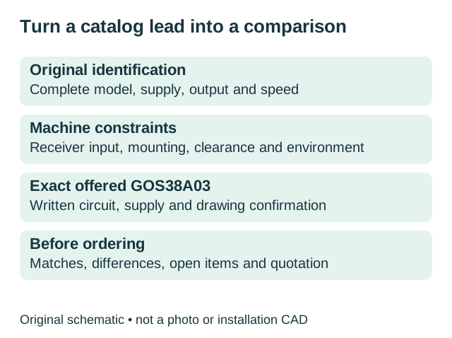
Provide the full original label code. Add measured supply, receiver model, required speed, mounting option, cable details, quantity and destination if known. Ask for documented matches, differences and open items before ordering. Name, email and the original model are required to start. Optional technical details can be marked Unknown; keep leading zeros in the original model.
Ready to contact us? Copy the prepared request, then open the live web inquiry form and paste the details. Preview sends nothing.
OVW2 replacement questions
Does OVW2-10 mean 10 pulses per revolution?
No. In the reviewed original ordering table, code 10 means 1,000 P/R. Keep leading zeros: 006 is 60 P/R while 06 is 600 P/R.
Can I replace HC with HCP?
Do not assume compatibility. HC uses an NPN open-collector circuit; HCP is PNP open collector and has a different frequency response in the reviewed original. Check the receiver and exact offered specification.
Does every OVW2 use a 28 mm mounting pitch?
The reviewed drawing shows standard PCD28 and option A PCD30. Inspect the complete original model and compare both actual drawings.
Is the listed GOS38A03 pair ready to install?
It is an initial catalog reference. Resolve output and supply conflicts, verify the receiver and dimensions, and obtain the exact offered-item documents before installation.
Sources and maintenance
- Nemicon OVW-2 original catalog mirrored by e-pwr, historical 2005 document, printed pages 30–31: ordering, dimensions, circuits and ratings.
- Original catalog copy hosted by ArtisanTG, printed pages 30–31 within a distributor cover. The cover’s commercial offer is separate from manufacturer specifications.
- Nemicon official site and official news and catalog updates: routes to current documentation and manufacturer inquiry.
- Reviewed Zhejiang Chengyao 2025 product sample, physical page 19, and existing EncoderCross candidate table. Candidate conflicts and conditions are retained above.
Maintained by EncoderCross for model-specific comparison inquiries. Revised 12 October 2026. Original diagrams are schematics. Historical original ratings are not a current offered-product approval.