01 / Signal path
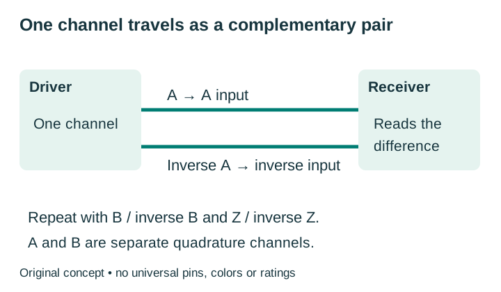
Pair A with inverse A, not with B
A complement has the opposite logical state to its channel. For differential ABZ outputs, the typical pairs are A / inverse A, B / inverse B and Z / inverse Z. Manufacturers may mark complements with a bar, slash or minus sign. Verify the connector’s actual functions before wiring.
A and B are the two quadrature channels used to decode direction. Inverse A is the complement of A, not another direction channel and not the supply return. Do not connect complementary outputs together or ground them by assumption.
Twisting each channel with its complement helps keep interference similar on both conductors. A suitable receiver rejects a common disturbance within its specified operating range. This does not make the installation immune to noise, eliminate reference requirements or permit arbitrary voltage differences between equipment.
Beckhoff’s EL5101-00x0 documentation is a useful example of why the suffix matters: EL5101-0010 and -0011 do not support single-ended connection. Follow the exact receiver’s permitted input mode rather than adapting a generic sketch.
02 / Names and voltage
TTL, HTL and RS-422 do not answer the same question
| Label | What to investigate | What remains unproven |
|---|---|---|
| TTL / 5 V output | Specified logic levels, load and whether outputs are paired | Encoder supply range and full receiver compatibility |
| HTL / push-pull | Actual high/low levels and source/sink capability | Differential operation or acceptance by a 5 V input |
| RS-422 differential | Driver and receiver electrical limits, pair polarity and reference | Application protocol, connector assignment or unlimited cable length |
| 7272 / 4469 / 26LS31 | Exact chip version, encoder implementation and output option | A complete encoder specification from the chip name alone |
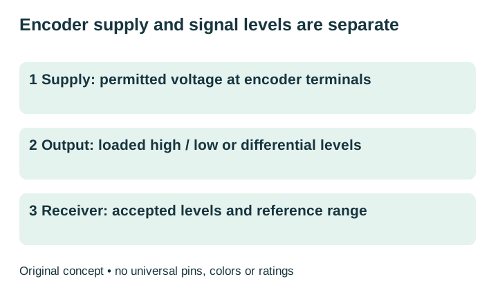
Loaded output levels are the voltages with the intended input and termination connected. Some encoders accept a higher supply while regulating their output to a lower level. Others produce signals related to the supply. Obtain the exact output specification rather than connecting a higher-voltage output to a lower-voltage input.
EPC’s TB-109 distinguishes its HV and H5 options: the stated RS-422 condition for HV is operation at 5 V; H5 is a regulated 5 V output option on specified models. These are EPC examples, not definitions of every brand’s suffix.
“5 V output” also does not mean an ideal 0-to-5 V square wave under every load. TI’s AM26LS31 datasheet specifies output high/low values under defined current, supply and temperature conditions. Use the documented limits, not an unloaded sketch. Do not modify an encoder’s circuit to change its output type.
03 / Replacement evidence
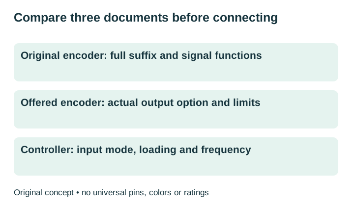
Compare the original, offered encoder and receiver
| Check | Original / offered encoders | Receiver requirement |
|---|---|---|
| Supply | Permitted voltage at the encoder, consumption and power-up behavior | Supply capability and return arrangement |
| Signal | Output circuit, loaded levels, pair functions and polarity | Accepted differential levels, common-mode range or permitted single-ended mode |
| Load | Allowed load and thermal conditions | Input impedance, bias (the circuit that sets an idle level) and built-in / switchable termination |
| Timing | PPR definition, output frequency and index characteristics | Input frequency, decode mode, filtering and index requirements |
| Cable | Exact connector, recommended cable and documented limits | Pairing, reference, shield and termination instructions |
Record each result as confirmed, different or unresolved. A full original model and exact proposed suffix are more useful than “same voltage” or “same pulses”. Use the encoder wiring guide to map the documented functions; keep this worksheet for driver and receiver acceptance.
04 / Termination
Check existing termination before adding another resistor
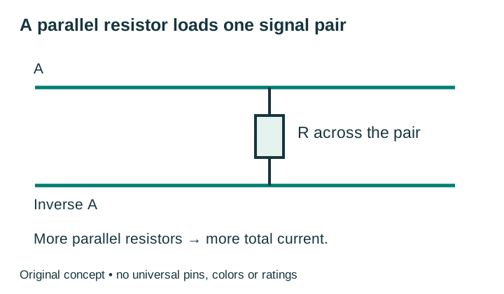
A parallel termination is a resistor across a signal pair; it is not an open-collector pull-up. Its purpose and placement differ. TI’s RS-422 application guidance places a termination, if used, near the last receiver. Confirm the encoder and controller instructions, including any internal or switchable resistor, before adding an external one.
Resistive load estimate for one channel pair
One pair only. This tool does not select a termination resistor or approve an interface.
Enter the differential voltage and resistance.
Arithmetic, not an approval: for N identical parallel resistors, equivalent resistance = R/N; total current = N × |V|/R; each resistor’s power = V²/R. Use the voltage across the pair, not the encoder’s supply voltage.
Example only: 3 V across 120 Ω gives 25 mA and 75 mW. Two equal resistors across that same pair give 60 Ω and 50 mA total. This does not recommend 120 Ω or establish any driver’s current limit.
Without JavaScript, use the same formulas. The estimate assumes steady resistive loading and excludes receiver bias, cable effects and switching transients. It displays up to three decimal places; very small values may round to zero. It does not calculate whole-encoder supply current or select a resistor rating.
Compare the complete load with the actual driver’s operating limits. A chip’s short-circuit current is not its continuous operating rating. Mixed resistor values, active inputs and multiple receivers need a complete circuit review.
05 / Operating point
There is no universal line-driver cable distance
Record cable length, pair construction, conductor resistance, capacitance, routing and receiving-end waveform. Check supply voltage at the encoder as well as signal quality at the controller. A capable driver cannot compensate for an encoder supply that falls below its permitted range.
Maxon’s long-cable guidance treats supply drop and signal-driver capability as separate constraints. A supply-drop calculation alone does not approve a transmission distance. Temperature, cable and actual input loading still matter.
Calculate the channel cycle frequency from the manufacturer’s pulse definition and maximum working speed, then compare it with the encoder output and receiver limits. Decoded counts per second can differ from channel frequency. The PPR and frequency guide covers the arithmetic.
Confirm the equipment’s shield and reference arrangement. Differential inputs still have an allowed common-mode range—the range of voltage shared by the two input conductors relative to the receiver’s reference. A shield is not a substitute for the specified supply return or reference connection.
06 / Missed counts
Gather evidence before replacing the encoder
| Observed symptom | Evidence to collect | Next decision |
|---|---|---|
| No counts | Encoder supply, receiver mode, pair functions and channel activity | Resolve the first mismatch before selecting a new output |
| Errors increase with speed | Receiving-end differential waveform, frequency limits, filters and load | Check timing margin and signal integrity |
| Counts change when a drive switches | Routing, reference, shielding and common-mode conditions | Review the installation against both manuals |
| Output drops after warming | Supply, full load and permitted operating temperature | Investigate operating conditions; do not assume a faulty chip |
| Direction or index is wrong | Pair polarity, channel mapping, decoder mode and index definition | Confirm mapping and settings without discarding complements |
Isolate power before changing connections. Live measurements require suitable differential or isolated instrumentation and a qualified person following the machine procedure. Do not connect an ordinary grounded probe clip to a signal output by assumption.
If a replacement is needed, start from the installed Omron E6B2 or Autonics E40S family and retain the complete output suffix. Confirm mechanical fit separately with the drawing; this page does not establish a universal replacement.
Request the missing interface evidence07 / Next decision
Request an encoder line-driver comparison
Provide the full original model, supply, receiving controller, cable length and existing termination if known. Include working speed, PPR and the symptom. Ask for the complete offered code, output circuit and loaded ratings, plus a written list of confirmed matches, differences and unresolved conditions. Mark unknown values as unknown.
Name, email and original model are required to start. Availability, price and delivery need a written quotation; no stock or response-time promise is implied.
Ready to contact us? Copy the prepared request, then open the live web inquiry form and paste the details. Preview sends nothing.
Encoder line-driver questions
Is every line driver differential?
No. The name alone does not establish the output circuit. Confirm complementary outputs, loaded ratings and the receiving input.
Can a higher-supply encoder have a 5 V output?
Yes, where the exact output option documents that behavior. Check the encoder supply range and output levels separately.
Can I use only A and B and ignore the complements?
Only with an explicitly supported single-ended method and compatible levels. That connection does not provide differential reception; some receiver variants do not support it.
Should I add a 120 Ω resistor?
Only if the exact equipment requires that value and location and the complete load is permitted. Check internal termination first. The calculator is an arithmetic example, not a resistor recommendation.
Does RS-422 mean the encoder supports Modbus or an absolute protocol?
No. An electrical interface label does not identify the application protocol. This guide concerns incremental channel signals.
Sources and maintenance
- EPC TB-109: Specifying Output Types, Rev D, 3 November 2017; output circuits and HV/H5 examples.
- Texas Instruments AM26LS31 datasheet, SLLS114N, revised June 2026; loaded output conditions and RS-422 application/termination guidance, physical pages 5–6 and 11–14.
- Same Sky: Common Encoder Output Signals, output stages and complementary-pair explanation.
- Maxon: Encoder Line Driver and long-cable guidance, updated 29 August 2024; receiver and supply-drop distinctions.
- Beckhoff EL5101-00x0 connection documentation, exact receiver-variant restrictions.
Maintained by EncoderCross. Reviewed 14 October 2026. Original diagrams explain functions; they are not product wiring drawings. This page covers driver and receiver acceptance; linked guides cover wiring functions and pulse-rate calculations. Recheck the exact documents whenever a suffix, cable or receiver changes. Brand names identify equipment and do not imply affiliation.