01 / Identify the circuit
NPN, PNP, push-pull and differential outputs
| Output | How it behaves | Verify before connecting |
|---|---|---|
| NPN open collector | Sinks current toward signal common when active | Input current path, pull-up arrangement, load and levels |
| PNP open collector | Sources current from the supply side when active | Input return path, load, polarity and levels |
| Push-pull / totem-pole | Actively drives high and low states | High/low levels and source/sink ratings under load |
| Differential line driver | Provides a channel and its inverted partner for a differential receiver | Compatible differential receiver, pairs and common-mode limits |
| Voltage output | May use an internal pull-up circuit | Original circuit, load and high-level voltage; do not assume push-pull |
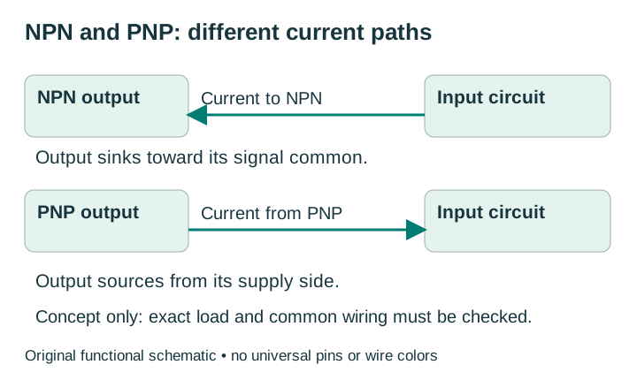
PLC terms such as sourcing and sinking can describe different sides of the connection. Read the actual input circuit rather than matching a word. Check whether a pull-up or input load is already built in; adding another resistor changes the load and the waveform.
TTL, HTL and RS-422 labels need exact specifications. Supply range, signal level and receiver acceptance are separate. A push-pull output described as complementary does not automatically provide separate A-bar, B-bar and Z-bar wires.
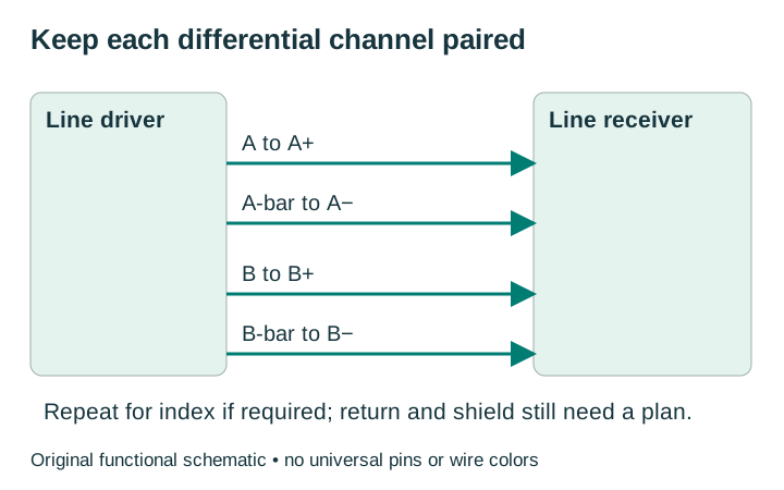
Paired inverse signals alone do not establish RS-422 electrical compatibility. Unused inverse outputs are not automatically connected to 0 V. If single-ended operation is permitted, follow the receiver’s documented method. For example, Beckhoff explicitly excludes single-ended connection on EL5101-0010 and EL5101-0011. A generic adapter sketch cannot override that restriction.
02 / Missing-document check
Find the next interface checks
The result is a documentation checklist, not a connection verdict.
Select only what the equipment documentation establishes. The aid lists questions for the proposed connection; it does not approve wiring or choose resistor values.
Identify both exact equipment models and their circuits.
Without JavaScript, use the output table and connection checklist. Document unknowns instead of trying a wire combination.
03 / Document the connection
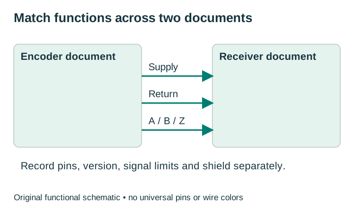
Map functions before colors or connector pins
| Function | Encoder evidence | Receiver evidence |
|---|---|---|
| +V and return | Allowed supply, current and cable drop | Supply capacity and documented reference |
| A / B | Terminal, levels, load, phase relation | Correct high-speed inputs and configured mode |
| Z / index | Presence, polarity, pulse width and gating | Supported index/latch behavior and timing |
| A-bar / B-bar / Z-bar | Separate inverse channels if provided | Matching negative inputs if required |
| Shield / case | Internal bonding and connection option | Specified shield termination / EMC arrangement |
Record connector gender, coding and the drawing’s viewing side. Matching M12 size or pin count does not prove a compatible assignment. Do not join signal outputs together. Keep motor-power conductors separate from encoder supply and signal conductors.
04 / Signal integrity
Cable routing, shield and signal common are different checks
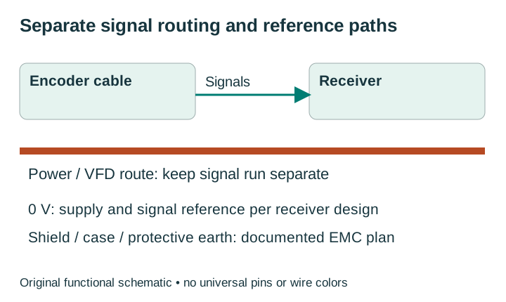
Use the specified cable construction and keep signal routing separate from high-current conductors, motors and drive cables. Preserve differential channel pairs. Minimize unnecessary splices; where a junction is unavoidable, check continuity, pairing, shielding and environmental protection.
The supply return carries operating current; the signal reference establishes the receiver’s reference potential. The cable shield and protective earth serve different purposes. Follow the receiver’s isolation and bonding design rather than joining them by assumption. Follow the encoder, receiver and machine EMC instructions, including any internal shield-to-case bond. Never remove required protective-earth connections to cure noise.
The reviewed EPC Rev 11/18 guide shows shield termination at the controller end with the encoder end unconnected. Treat it as that guide’s arrangement, not a universal instruction for every machine. If equipment instructions disagree, resolve the bonding plan before installation.
Do not add a generic 120 Ω resistor to every encoder. Termination depends on the driver, cable and receiver, including built-in termination. An open-collector pull-up and a differential termination are different components. A resistor that overloads an output can distort signals or damage it.
No single cable-length number applies to all interfaces. Verify signal quality at the receiver at the intended speed, plus supply voltage at the encoder under load. See an example of supply and output-code separation →
05 / Controlled commissioning
Check a short sequence before normal operation
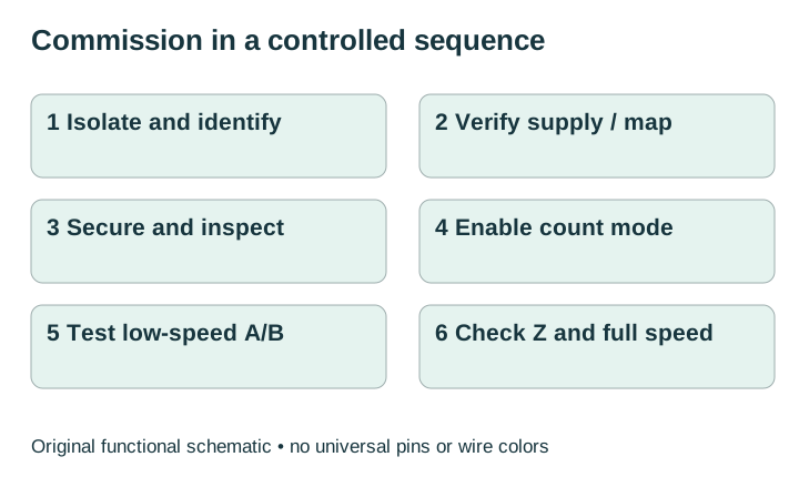
- Isolate power and identify the documents. Confirm full models, receiver version and terminal map before changing wires.
- Check supply and the connection map. Use the correct voltage, polarity, references and supported channels. Inspect continuity with equipment isolated as instructed.
- Secure connections and cable. Confirm strain relief, connector assembly, shield arrangement and unused-wire insulation.
- Configure the receiver. Select the intended quadrature / pulse mode, high-speed inputs, filter, count multiplier and index behavior.
- Test controlled low-speed motion. Compare A/B and count direction with a stated shaft viewing side. Use the documented receiver or machine method for any direction change, then recheck index alignment; do not swap wires casually in a feedback loop.
- Verify the operating point. Check waveform quality and timing at the receiver at intended speed, within both encoder and receiver limits.
For illustrative 2,500 PPR at 1,500 rpm, raw channel frequency is 2,500 × 1,500 ÷ 60 = 62,500 Hz. ×4 decoding produces 250,000 counts/s. Check both limits; input filters can also reject narrow pulses. These are arithmetic inputs, not a supported rating for a particular encoder. Use the PPR and count-rate guide for calculations →
06 / Symptoms
Use the symptom to choose the next measurement
| Symptom | First checks | Next evidence |
|---|---|---|
| No counts | Actual shaft movement, supply at encoder, wiring and receiver mode | Documented signal at receiver; correct input circuit |
| Wrong direction | A/B relationship, viewing side and software direction setting | Both channels and required index alignment |
| Extra / erratic counts | Loose connections, supply noise, EMC plan and mechanical slip | Waveform during drive switching / actual operation |
| Misses at speed | Raw Hz, decoded count limit, rise/fall time and input filter | Receiver waveform at intended speed |
| Index not detected | Z present, polarity, gating and receiver capture mode | Index waveform and pulse duration; a meter may miss it |
Use measurement equipment and probing methods suitable for the circuit. An oscilloscope ground connection can change a reference path; use the machine’s approved procedure. Record the test conditions before requesting a replacement. Request a comparison using your exact model and receiver →
07 / Model-specific next step
Request an encoder and receiver wiring comparison
Provide the full original label model, receiver model, supply, output circuit, cable length and symptom if known. Ask for a comparison of documented functions, levels and unresolved conditions. Name, email and the original model are required; unknown receiver details can be described in the message.
Ready to contact us? Copy the prepared request, then open the live web inquiry form and paste the details. Preview sends nothing.
Encoder wiring questions
Is there a universal five-wire or eight-wire color code?
No. Use the exact encoder and cable documents. Wire count does not identify the circuit, connector assignment or internal bonding.
Can I connect a 24 V supply encoder to a 5 V input?
Only if its actual output levels, circuit and references meet that input’s requirements. Supply voltage alone cannot answer the question.
Can I ground the inverse outputs?
Do not infer that from a generic sketch. Follow the receiver’s documented single-ended method if supported; some receiver variants require differential pairs.
Will a pull-up or 120 Ω resistor solve missed counts?
Not automatically. Check built-in loading, driver capability, wiring, waveform, receiver mode and filter first. Select any external resistor only from the exact circuit requirements.
Which replacement guide should I use?
Start from the installed family: Omron E6B2, Autonics E40S or Nemicon OVW2. A catalog lead still needs its own output and receiver comparison.
Sources and maintenance
- Encoder Products Company installation and wiring guide, Rev 11/18, electrical connection/circuits and troubleshooting; physical pages 8–10 and 15.
- OMRON rotary encoder connection examples and CSM_Rotary_TG_E_7_2 technical explanation, circuit definitions and specified encoder/receiver distinctions.
- Beckhoff EL5101-00x0 connection page, supply, signal terminals and single-ended variant restrictions. Use the exact receiver suffix and hardware documentation.
- Dynapar wiring practices, routing, signal quality and phasing context.
Maintained by EncoderCross. Reviewed 13 October 2026. The connection worksheet is the main task; the linked PPR guide covers rate calculations in detail. Original diagrams show functions, not universal pinouts. Review the connection whenever equipment or document versions change. Brand names identify equipment and do not imply affiliation.